Groupe : C.M.O. SpA

Extraits du catalogue

SOLENOID VALVES 10mm ELECTROVALVES 10 mm ELETTROVALVOLA 10 mm The solenoid valves directly controlled are suitable for assembling on multiple or single bases; they have a low consumption of energy and have a small monostable control for an eventual manual intervention. L'électropilote à commande directe est particulièrement indiqué pour des montages sur embase multiple ou simple. Il a une faible consommation d'énergie et a une commande manuelle pour d'éventuelles interventions. Gli elettropiloti a comando diretto sono particolarmente indicati per montaggio su basi multiple oppure su basi singole, permettono un basso assorbimento di energia ed hanno un piccolo comando monostabile per intervento manuale. 10 mm STDDATI TECNICI rico DIMENSIONS t / utilizzo TECHNICAL/DATA / DONNÉES TECHNIQUES / DIMENSIONS 3. exhaust scarico Miniature Solenoid Valves E.V. 10 mm 3/2 STD Miniature Solenoid Valves E.V. 10 mm 3/2 STD Max working temperature / Température max d'utilisation / Temperatura max di esercizio SOLENOID VALVES 10 mm / ELECTROVALVES 10 mm / ELETTROVALVOLA 10 mm Type / Type / Tipo Max operating pressure / Pression max d'utilisation / Pressione massima di esercizio Flow rate to 6 bar and Δp 1 bar / Débit à 6 bar et Δp 1 bar / Portata a 6 bar e Δp 1 bar Nominal orifice / Diamétre nominal / Diametro nominale SOLENOID VALVES 10 mm / ELECTROVALVES 10 mm / ELETTROVALVOLA 10 mm Valves / Valves / Valvole Miniature Solenoid Valves 3/2 STD E.V. 10 mm Life time / Durée / Durata cicli >50 millions cycles / >50 millions de cycles / >50 milioni di cicli Tension tolerance / Tolérance de tension / Tolleranza di tensione Response time / Temps de réponse / Tempo di risposta Duty cycle / Temps d'enclenchement / Inserimento Voltage / Voltage / Voltaggio Rated power consumption / Consommation / Consumo a regime Protection / Protection / Protezione FUNCTIONAL SCHEMATIC AND INSTALLATION / SCHÉMA FONCTIONNEMENT ET MONTAGE / SCHEMA FUNZIONAMENTO E ISTALLAZIONE Functional schematic Schéma de fonctionnement Schema funzionamento Sub-base installation Installation embase Istallazione sottobase Valve installation Installation de vanne Installazione della valvola (Normally closed) ormalmente chiusa) VOLTAGE / WATTAGE (R) ELECTRICAL CONNECTION - (MANUAL OVERRIDE OPTIONS) (A) FUNCTION VOLTAGE / WATTAGE / (R) ELECTRICAL CONNECTION - (MANUAL OVERRIDE OPTIONS) (A) N) 6 (OFF) 2 = without manual override A = Free exhaust 6 = 2/2 NC 1 = 24 Vdc 1.3 W R = Rotated 1 = 90° Connector + Led & suppressor diode A = Free exhaust 6 Coil NC 2 =1Encapsulated Cables 300 mm (IP65 no electronics) 1 = 90°8Connector + Led & suppressor diode (in atmosphere) 2 = without manual override = 2/2 = 24 Vdc 1.3 W R = Rotated 24 V DC = 2-position manual override 7 = 3/2 NC 2 = 12 Vdc 1.3 W (in atmosphere) 3/2 NC only 180° Coil 8 = 2-position manual override 7 = 3/2 NC 3 =2Line ConnectorW Led & suppressor diode = 12 Vdc 1.3 + 2 = Encapsulated Cables 300 mm (IP65 no electronics) 3/2 NC only ( ) = push & release 8 = 3/2 NO 3 = 24 Vac 1.3 W 180° ECTION ** W - (MANUAL OVERRIDE OPTIONS) (A) manual Led & (default) 0.9 * 3.5/0.3 ( ) = push & release 8 = 3/2 NO 4 =390°24 Vac 1.3 W = Connector without Led 3 = Line Connector +overridesuppressor diode 4 = 6 Vdc 1.3 W manual override (default) ° or 180 2 % 2 a simple manual possible to rotate the A= pressor diode With= withoutclick, it isoverride Free exhaust connection by 90 = 6 Vdc 1.3 W° thus 4 = 90° 0° Connector without Led 90° 180° 5 24 Vdc 0.6 W 5 =4Line Connector without Led (in supply cable. 12 10 facilitating the laying of the=poweratmosphere) V 5PINs with flat cover without Led = 24 Vdc 0.6 W 5 = Line Connector without Led 8 = 2-position manual override W mAC (IP65 no electronics) 6 = 5 Vdc 1.3 6= CONNECTION ROTATION / CONNEXION ROTATION / ROTAZIONE CONNESSIONE 9 Cables 100 mm+Molex M. 14 = = 12 Vdc 0.9 W S.U. Analog(p/n 51006-0200) Con un semplice click, è possibile ruotare la connessione di 90° = 24 Vdc 0.3 W PWM Digital A o 180° faciliMilion cycles B = 12 Vdc 0.3 W PWM Digital 15 = Cables 100 mm+Tyco MODU II (p/n 280358-0) tando suppressor diode così la stesura del cavo di alimentazione elettrica. B = 12 Vdc 0.3 W PWM Digital rews M1.7 9 = Spring contacts for PCB (upon inquiry) 15 = Cables 100 mm+Tyco MODU II (p/n 280358-0) 18 = Cables 100 mm+Molex F. (p/n 51065-0200) Example: N371/1-A = 10 mm STD 3/2 NC Ø 0.7 mm 7 bar 24 Vdc 1.3 W 90° Connector+Led P&R manual override free exhaust Example: N371/1-A = 10 mm STD 3/2 NC Ø 0.7 mm 7 bar 24 Vdc 1.3 W 90° Connector+Led P&R manual override free exhaust Edition 2021 rev. 0 8 = Cover cap + Cables 300 mm (IP51 with electronics) = 12 contacts 8 = Cover cap + Cables 300 mm (IP51 with electronics) 9 =8SpringVdc 0.6 Wfor PCB (upon inquiry) ou 180 ° facilitant ainsi la pose du câble d'alimentation. QUALITY 7 = PINs with flat cover + Led & suppressor diode 6 = PINs with flat cover without Led 3/2 NC only = 5 with flat pressor diode ( ) = push & release 7 = 24 Vdc S.U. Analog 7 =6PINs Vdc 1.3 W Led & Avec un simple clic, il (default) 0.9 Wde faire pivoter la connexion de cover °+Analog suppressor diode manual overr
Ouvrir le catalogue en page 1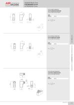
SOLENOID VALVES 10mm ELECTROVALVES 10 mm ELETTROVALVOLA 10 mm 3/2 NC LOWER CONNECTOR 3/2 NF CONNECTEUR INFERIEUR 3/2 NC CONNETTORE INFERIORE CODE EP50221 Valves / Valves / Valvole 3/2 NC LATERALE CONNECTOR 3/2 NF CONNECTEUR LATERAL 3/2 NC CONNETTORE LATERALE CODE EP50220 SOLENOID VALVES 10 mm / ELECTROVALVES 10 mm / ELETTROVALVOLA 10 mm 3/2 NC WITH M8 CONNECTOR 3/2 NF AVEC CONNECTEUR M8 3/2 NC CON CONNETTORE M8 CODE EP50223
Ouvrir le catalogue en page 2
SOLENOID VALVES 10 mm ELECTROVALVES 10 mm ELETTROVALVOLA 10 mm SINGLE MANIFOLD EMBASE SIMPLE BASE SINGOLA CODE SB4010101 Valves / Valves / Valvole MANIFOLD EMBASE MULTIPLE BASE MULTIPLA SOLENOID VALVES 10 mm / ELECTROVALVES 10 mm / ELETTROVALVOLA 10 mm CONNECTORS CONNECTEUR CONNETTORI CODE VX0048 VX0049 VX0050
Ouvrir le catalogue en page 3Tous les catalogues et fiches techniques (PDF) Airwork Pneumatic Equipment
-
 VP
VP4 Pages
-
 RACCORDS À COIFFE
10 Pages
-
 MICROVALVES
6 Pages
-
 CG series
14 Pages
-
 CF series
14 Pages
-
 MC
MC12 Pages
-
 MX
MX6 Pages
-
 CT
CT8 Pages
-
 CY VERINS 15552 - SERIE CY
14 Pages
-
 VMIC
VMIC6 Pages
-
 VDM
VDM3 Pages
-
 VY
VY16 Pages
-
 CZ
CZ14 Pages
-
 CQ
CQ8 Pages
-
 CA
CA4 Pages
-
 CM
CM8 Pages
-
 AR
AR3 Pages
-
 CX
CX6 Pages
-
 CP
CP5 Pages
-
 CH
CH2 Pages
-
 CC6
CC68 Pages
-
 CC
CC4 Pages
-
 CD
CD9 Pages
-
 SS
SS11 Pages
-
 BS
BS4 Pages
-
 BS2
BS23 Pages
-
 ST
ST5 Pages
-
 UG
UG8 Pages
-
 RY
RY4 Pages
-
 AT
AT6 Pages
-
 RI
RI10 Pages
-
 PA
PA4 Pages
-
 PG
PG3 Pages
-
 PS
PS5 Pages
-
 PH
PH4 Pages
-
 PX
PX4 Pages
-
 EP
EP2 Pages
-
 VD
VD3 Pages
-
 VK
VK8 Pages
-
 VA
VA12 Pages
-
 VB
VB10 Pages
-
 VH2
VH216 Pages
-
 VI
VI7 Pages
-
 VU
VU4 Pages
-
 VMA2
VMA29 Pages
-
 VMEC
VMEC4 Pages
-
 RF
RF1 Pages
-
 RFX
RFX1 Pages
-
 VR4
VR41 Pages
-
 VRX1
VRX11 Pages
-
 VRNR
VRNR2 Pages
-
 VRX
VRX1 Pages
-
 VS
VS1 Pages
-
 VO
VO2 Pages
-
 VR
VR1 Pages
-
 BV0
BV03 Pages
-
 SI
SI3 Pages
-
 VQI
VQI6 Pages
-
 VQM
VQM3 Pages
-
 VQS
VQS4 Pages
-
 XM0
XM01 Pages
-
 XF0
XF01 Pages
-
 XC0
XC01 Pages
-
 XR0
XR01 Pages
-
 XQ
XQ1 Pages
-
 XP0
XP01 Pages
-
 XL0
XL01 Pages
-
 XS0
XS01 Pages
-
 XT0
XT01 Pages
-
 XF1
XF12 Pages
-
 XC FILTRE A COALESCENCE
1 Pages
-
 XR1
XR11 Pages
-
 XP1
XP12 Pages
-
 XL1
XL12 Pages
-
 XS1
XS11 Pages
-
 XT
XT1 Pages
-
 XA1
XA11 Pages
-
 XV1
XV12 Pages
-
 XO1
XO11 Pages
-
 XD
XD1 Pages
-
 XM
XM1 Pages
-
 XN
XN1 Pages
-
 XB
XB4 Pages
-
 YF
YF1 Pages
-
 YC
YC1 Pages
-
 YR
YR1 Pages
-
 YP
YP1 Pages
-
 YL
YL1 Pages
-
 YS
YS1 Pages
-
 YT
YT1 Pages
-
 YO
YO1 Pages
-
 YD
YD1 Pages
-
 YE
YE1 Pages
-
 YJ
YJ1 Pages
-
 YU
YU1 Pages
-
 YB ACCESSOIRES
1 Pages
-
 PC
PC13 Pages
-
 A100
A10012 Pages
-
 A100X
A100X5 Pages
-
 NSC
NSC8 Pages
-
 B200
B20012 Pages
-
 C300
C30010 Pages
-
 D400
D4005 Pages
-
 TUBES PNEUMATIQUES
7 Pages
-
 E500
E5006 Pages
-
 YV
YV1 Pages
-
 RACCORDS
83 Pages
-
 TRAITEMENT D'AIR
61 Pages
-
 ACTIONNEURS
161 Pages
-
 VALVES
147 Pages
-
 General catalogue 2024
497 Pages
-
 General catalogue
472 Pages
-
 General catalogue - VALVES
147 Pages
-
 Airwork-General catalog
472 Pages


