
Extraits du catalogue
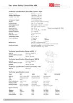
Data sheet Safety Contact Mat ASK Technical specifications for safety contact mats Max. Dimension: 2500 mm x 1400 mm Standard dimensions: 1000 mm x 750 mm available from stock 1000 mm x 1000 mm 1000 mm x 1500 mm Construction height: 14 mm with covering Weight: approx. 15 kg/m² (without covering) Inactive border: max. 10 mm on all sides Switching pressure: Round body 80 mm = ca. 150 N Static load: max. 2000 N over 80 mm * Response time: max. 25 ms * Switching cycles: min. 1,5 Mio. (B10d: 2.000.000)* Electrical Capacity: 24 V 100 mA Material: Polyurethane black Protection class: IP 65...
Ouvrir le catalogue en page 4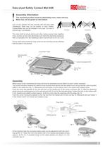
Data sheet Safety Contact Mat ASK ! Lay out and position the mat correctly with the base plate downwards. Mats may not be broken or bent. Safety- Contact-Mats may not be changed in any way. Cut outs or shortening is not possible. The mats shall be joined end-to-end when laying several mats together. Then connect up the mats electrically and check the electrical resistance. With un-actuated mat, the resistance value must amount to 8,2 kW ± 2%. During cable laying inside the ramp- and/or in the mounting rail pay attention that the cable is not pinched. Connection Cable Corner Connector EVA...
Ouvrir le catalogue en page 5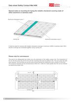
Data sheet Safety Contact Mat ASK Special notes on mounting for laying the metallic checkered covering made of either aluminum or stainless steel Aluminum-checkered cover 1 Joining rail Aluminum-checkered cover 2 It shall be noted for versions with metallic checkered coverings in aluminum (ARB) or stainless steel (TBV) that the coverings are connected together using a joining rail.. Please note for overmeasure The area to be safeguarded are made up by the dimension of the safety contact mat. The dimensions of 62 mm (for the ramp rail) and 35 mm (for the mounting-rail) must be added to this....
Ouvrir le catalogue en page 6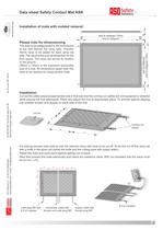
====== Installation Cut out the cable output at appropriate side in that way that the coming out cables are not squeezed or sheared while placing the mat afterwards. Place and adjust the mat at appropriate place. To provide against slipping use suitable screws and dowels on each side of the mat. 8,2 kÙ resistor Ù ==== cut out coming out cables supply cable with female plug M8 connection cable with female and male plug M8 male plug M8 with 8,2 kÙ resistor Installation of mats with molded ramprail 16.DB.00.002 Technical data rev 06 as of June 29th 2010 Technical changes reserved Am Grarock 8...
Ouvrir le catalogue en page 7Tous les catalogues et fiches techniques (PDF) ASO GmbH
-
Pare chocs ASB
6 Pages
-
Barres palpeuses GE-serie
7 Pages
-
Catalogue des produits
36 Pages
-
INDUS Compact
84 Pages
-
GE F115 SK
2 Pages
-
GE F65 ST
2 Pages
-
GE F50 FKLi
2 Pages
-
GE F45 ST
2 Pages
-
Safety contact edges
7 Pages


