- Catalogues
- Omniflex
- Model M1031B BASE
- Produits
- Catalogues
- News & Trends
- Salons
Model M1031B BASE
1 /3Pages

Model M1031B BASE
1 /3Pages
Extraits du catalogue

DATASHEET FEATURES • Wall- mounting System sizes from 2 to 15 I/O modules per CPU Secure easy-to-use module mounting. Automatic I/O module slot addressing Automatic I/O module type identification Optional module keying 19” frame adapter available MAXIFLEX Bases are available in various sizes (for application flexibility and to cater for possible enclosure limitations). These bases are designed for surface mounting but a purpose designed mounting bracket (Model M1821) facilitates mounting in a 19” frame. Two types of base are available in this range: Master Bases and Expander Bases. Every Master Base will accept a CPU module plus a number of I/O modules, while the Expander Bases accept only I/O modules. The number of I/O modules accessed by the CPU on any Master Base, (except the M1001 2I/O base which does not have an expander socket), may be expanded using any one of the Expander Bases. A single Expander Base is connected to a Master Base using the M1811 Expander Cable. This allows a maximum of 15 I/O modules to be connected to a single CPU module. The M1811 Expander Cable is 400mm long, allowing a maximum of 180mm between the Master and Expander bases when mounted one above the other. A space of least 100mm must be allowed between bases when mounted to allow for module insertion/removal and field wiring. Each MAXIFLEX module is secured in position on the base by a retaining clip that is pressed to remove the module. Each Master base in the range requires a logic power supply to power the system. An additional logic power supply is required for the 8 way expander base. SPECIFICATIONS Model Weight Unpacked Weight Packed Environmental Operating Temperature: -25°C to +60°C (-13°F to +140°F) Copyright Omniflex ♦ Subject to change without notice
Ouvrir le catalogue en page 1
MECHANICAL DIMENSIONS 2 I/O Master 3 I/O Master 5 I/O Master 5 I/O Expander 7 I/O Master 8 I/O Expander Copyright Omniflex ♦ Subject to change without notice
Ouvrir le catalogue en page 2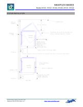
MAXIFLEX BASES SYSTEM INSTALLATION MAXIFLEX BASE CABINET ROOF CLEARANCE ABOVE MODULE REQUIRED FOR MODULE INSERTION/REMOVAL POSITION NETWORK CABLES WIRING ACCESS TO MODULES HERE 100 mm minimum (180 mm maximum for expansion base due to expansion cable length) WIRING CLEARANCE SIDE VIEW Copyright Omniflex ♦ Subject to change without notice
Ouvrir le catalogue en page 3Tous les catalogues et fiches techniques (PDF) Omniflex
 MAXIFLEX Bases
3 Pages
 CONET Local Area Network
8 Pages
 Model M1267B CPU P3e-R
8 Pages
 Model M1265A CPU A3e
8 Pages
 Model M1586A CONET PNIM
2 Pages
 Model M1588D HARWELL NIM
2 Pages
 Model M1711A HSC
2 Pages
 Model M1322A 16DI-24
2 Pages
 Model M1323A 16DI-48
2 Pages
 Model M1326A 32DI-24
2 Pages
 Model M1327A 64DI-24
2 Pages
 Model M1341B 16DO
2 Pages
 Model M1330A 8DI8RO
2 Pages
 Model M1342A 32DO
2 Pages
 Model M1372A 8RO
2 Pages
 Maxilarm
15 Pages
 Model C2321A Teleterm M2S
8 Pages
 Model C2330B-11-0
6 Pages
 Model C2330B-12-0
6 Pages
 Model M1403A 16AI
2 Pages
 Model M1412A 8AO
2 Pages
 Model M1431B 8 VC ISO
2 Pages
 Model M1432C 8 TC/mV ISO
3 Pages
 Model M1433B 6 RTD ISO
2 Pages
 Model C2360C-0-0 Teleterm M2
6 Pages
 Model C2360B-0-0 Teleterm M2
8 Pages
 C2404B
4 Pages
 C118xB series
4 Pages
 Model M1589D HART NIM
3 Pages
 Model M1580A Dual Serial NIM
2 Pages
 Model M1240B CPU T2
6 Pages
 Model MT8150x OIT 15 Inch
2 Pages
 Model MT8121x OIT 12.1 Inch
2 Pages
 Model MT8070iH OIT 7 Inch
2 Pages
 Model MT8100i OIT 10 Inch
2 Pages
 Model M1022B BASE
3 Pages
 Model C2475A OMNITERM LZD
6 Pages
 Model C2474A OMNITERM LZI
6 Pages
 Model C2166A PT-2000 24Vdc
3 Pages
 Model MT8104xh OIT 10.4 Inch
2 Pages
 Model M1102A PSU
2 Pages
 Model MT6070ih OIT 7 Inch
2 Pages
 Model MT6050i OIT 4.3 Inch
2 Pages
 Model M1023B BASE
3 Pages
 Model C2063B OMNITERM LPI
12 Pages
 Model M1021B BASE
3 Pages
 Model C2462A OT LPD
12 Pages
 Next Generation Signal Conditioners
12 Pages
 Industry Standard Alarm Annunciators
10 Pages


Catalogues archivés

- E/S numérique
- Module E/S
- Bloc de jonction
- E/S analogique
- Module E/S numérique
- Passerelle de communication
- Chargeur de batterie industriel
- Passerelle Ethernet
- IHM
- Module d'E/S bus de terrain
- Bloc de jonction à connexion à vis
- IHM à écran tactile
- Passerelle série
- Module E/S analogique
- E/S série
- IHM encastrable
- E/S déportées
- Bloc de jonction sur rail-DIN
- IHM LCD
- Chargeur de batterie plomb