- Catalogues
- SITEMA
- SITEMA Dispositif SERRA / KFH

- Société
- Produits
- Catalogues
- News & Trends
- Salons
Extraits du catalogue
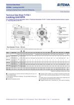
Technical Data Sheet SITEMA - Locking Unit KFH Locking by Spring Force / Hydraulic Releasing TI-F50-1-EN-07/2012 English translation of German original Technical Data Sheet TI-F50-1 Locking Unit KFH For a detailed functional description refer to”Technical Information TI-F10“. Further important practical advice is given in ”Operating Manual BA-F50“. , T2 L AG T ødf7/h6 w w KFH 36 and KFH 40 G1/8 30° HL 30° HT H2 v except KFH 36 and KFH 40 H1 H Rod diameter 18 mm - 60 mm KFH 28 KFH 32 KFH 36 KFH 40 KFH 45 KFH 50 KFH 56 KFH 60 Proximity switch port: 2 Signal ”released“ see 3 Information for KFH 25 - KFH 60: Due to tolerances ports 1 and 2 can be displaced up to +/-5° Ident.-No. 1 2 KFH 018 70 KFH 018 71 KFH 025 70 KFH 025 71 KFH 028 70 KFH 028 71 KFH 032 70 KFH 032 71 KFH 036 70 KFH 036 71 KFH 040 70 KFH 040 71 KFH 045 70 KFH 045 71 KFH 050 70 KFH 050 71 KFH 056 70 KFH 056 71 KFH 060 70 KFH 060 71 d F p D H L1 mm KFH 25 2 Dimensions Locking Unit KFH (CAD-files download at www.sitema.com) 1 KFH 18 Proximity switch port: 1 Signal ”clamped“ see 3 L1 øD øZH8 1 3x20° Type Port: pressure compensation 5 X+0,2 Fig. 1: Alternativ port: release pressure see 4 G Load direction 1 Load direction 2 AG Port: release pressure see 1 LL G1/8 kN bar mm mm mm 10 70 5 40 71 137 60 2x60° 12 M6 30 4 G1/8 6 20 100 12 50 95 140 82 2x60° 15 M8 50 6 G1/8 34 100 115 178 96 2x60° 18 M10 60 6 138 200 115 2x60° 18 M10 70 155 223 135 2x60° 20 M12 180 252 160 4x30° 20 M12 18 25 28 32 36 40 45 50 56 60 20 50 34 100 20 T2 G mm mm Z X AG HL H1 H2 HT cm3 mm mm mm mm 29 105 98 68 45° 4 11 19 89,5 83 62 35° 7 G1/4 18 20 118 112 94 30° 12 6 G1/4 28 19 109,5 119 96 30° 18 85 8 G1/4 39 20 147,5 140 108 30° 27 95 10 G1/4 47 22 151,5 144 105 30° 40 mm mm mm VL v Weight kg 50 50 w 100 35 55 50 100 35 55 75 100 45 75 75 100 45 75 100 100 70 70 100 100 70 70 Subject to modification without prior notice 1 F is guaranteed as nominal (minimum) holding force for dry or mineral oil wetted shafts. p is the pressure required for releasing. The permissible working pressure is 160 bar. 2 Hydraulic operating volume. 3 Proximity switch holders are provided for standard proximity switches M12x1 with a nominal switching distance of 2 mm (flush mounta- ble), except KFH 18 and KFH 25: M8x1 with a nominal distance of 1,5 mm. For easier service, the proximity switch holders have a depth stop and are pre-adjusted when delivered from the factory. 4 Plugged hydraulic port LL alternative to L, also useful for bleeding. 5 Spacers are provided to keep the unit released. To be removed after installation. SITEMA GmbH & Co.KG . Im Mittelfeld 10 . D-76135 Karlsruhe . Phone: +49(0)721/98661-0 . Fax: -11 . www.sitema.com 1/4
Ouvrir le catalogue en page 1Technical Data Sheet SITEMA - Locking Unit KFH Locking by Spring Force / Hydraulic Releasing TI-F50-1-EN-07/2012 Technical Data Sheet TI-F50-1 Locking Unit KFH For a detailed functional description refer to”Technical Information TI-F10“. Further important practical advice is given in ”Operating Manual BA-F51“. T2 T1 L T Port: pressure compensation 1 Proximity switch port: 1 Signal ”clamped“ see 3 L1 ødf7/h6 øD øZH8 Alternativ port: release pressure see 4 G Load direction 1 Load direction 2 G1/4 w w X+0,2 AG Port: release pressure see 1 LL G1/4 AG 3x20° 30° HL 30° HT H2 2 v Proximity switch...
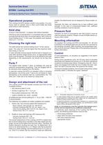
Ouvrir le catalogue en page 2Technical Data Sheet SITEMA - Locking Unit KFH Locking by Spring Force / Hydraulic Releasing TI-F50-1-EN-07/2012 Operational purpose The Locking Unit KFH clamps a shaft in any position. It is commonly used on cylinder rods or other round shafts and holds axial forces in both directions. Axial play A force in load direction 1 is always held without backlash. If the force acts in load direction 2, no backlash will occur either, provided that the force does not exceed approx. 80% of the nominal holding force F. In this case, the possible axial displacement is 0.1 - 0.3 mm. Choosing the right...
Ouvrir le catalogue en page 3Technical Data Sheet SITEMA - Locking Unit KFH Locking by Spring Force / Hydraulic Releasing TI-F50-1-EN-07/2012 Operating conditions The Locking Unit KFH is designed to operate in normal clean and dry workshop atmosphere. Operation in other environmental conditions is possible if at least port T is connected to a clean and dry atmosphere (e.g. tank). In case of heavy soiling conditions (grinding dust, chips, other liquids, etc.), please contact SITEMA. Viscous lubricants and grease may reduce the holding force. Regular functional checks The Locking Unit KFH must be functionally checked at...
Ouvrir le catalogue en page 4Tous les catalogues et fiches techniques (PDF) SITEMA
- PowerStroke SITEMA
9 Pages
- SITEMA_Flyer_2020
2 Pages
- TI-A10
7 Pages
- SITEMA Dispositif SERRA
6 Pages
- Company Brochure
15 Pages
- SITEMA dispositif FRENAX
1 Page
- electric Safety Brake linear
2 Pages
- TI-S10 Safety Locks
4 Pages
- TI-P30
1 Page
- Dimensions, type KRG
1 Page
- Dimensions, type KRP/T
1 Page
- Dimensions, type KRP
1 Page
- Dimensions, type KR, K
2 Pages
- SITEMA Safety Catchers
2 Pages
- STB10 Rod Attachment STB
3 Pages
- SITEMA Applications
2 Pages
- F60 Dimensions, type KFHA
6 Pages
- Z10 - Auto Bleeder
3 Pages
- Locking Units KFPC
3 Pages
- Vérin industrielle
- Dispositif de serrage
- Vérin double effet
- Table élévatrice industriel
- Vérin hydraulique
- Table élévatrice à ciseaux
- Vérin pneumatique
- Table élévatrice stationnaire
- Frein à friction
- Table élévatrice hydraulique
- Vérin industriel
- Vérin standard
- Frein électromagnétique
- Vérin ISO
- Bride de serrage hydraulique
- Système de contrôle pour l'industrie
- Table élévatrice pour charges lourdes
- Vérin à tige
- Frein de sécurité
- Système de contrôle de surveillance


